
Key Takeaways
- Most audit risk comes from confusing verification (a pass/fail check) with calibration (a comparison with documented uncertainty). An ice-point check is not a calibration.
- A thermocouple can pass lab calibration yet read incorrectly in your process due to inhomogeneity a change in the wire's properties that standard calibration can't detect.
- Your calibration certificate is incomplete without a GUM-compliant measurement uncertainty statement. Auditors will treat its absence as a systemic nonconformance.
- Use historical as-found data to trend thermocouple drift. This allows you to set evidence-based calibration intervals instead of relying on arbitrary annual schedules.
- The three most common audit findings are: calibration test points that don't match the process, missing as-found data, and an absent or indefensible uncertainty budget.
A heat-treat facility passes its annual thermocouple calibration event with flying colors. The certificates arrive, showing every sensor is well within its specified tolerance. Three months later, a surveillance audit grinds to a halt. The assessor flags the entire program, not because the work was done poorly, but because the records are metrologically indefensible. The certificates lack measurement uncertainty statements, as-found data is missing, and the test points have no documented connection to the actual furnace operating temperatures. The calibration was performed, but the evidence doesn't exist.
This scenario is more common than most quality managers or process engineers realize. Effective thermocouple calibration isn't just about following a procedure; it's about producing defensible proof that your measurements are fit for purpose. The value of the calibration is only as strong as the uncertainty analysis, drift evidence, and documentation behind it.
Most guides teach the mechanical steps. This one focuses on the metrological judgment that makes those steps stand up to scrutiny. We will cover the essential methods, a step-by-step procedure, the two factors that most often invalidate results between intervals inhomogeneity and drift how to build a defensible uncertainty budget, and what auditors actually scrutinize in your records.
Calibration vs. Verification: Why the Distinction Creates Audit Risk
In many facilities, the terms "calibration" and "verification" are used interchangeably. This common confusion creates significant audit risk because the two activities carry different metrological weight and produce fundamentally different records.
Calibration , as defined by the International Vocabulary of Metrology (VIM), is an operation that establishes a relationship between the quantity values with measurement uncertainties provided by measurement standards and corresponding indications with associated measurement uncertainties. In plain terms, you compare your thermocouple to a more accurate reference standard (like a Standard Platinum Resistance Thermometer or SPRT) and document the result along with a calculated measurement uncertainty.
Verification , by contrast, is the provision of objective evidence that a given item fulfills specified requirements. For a thermocouple, this typically means confirming it reads within a pass/fail tolerance.
Consider this frequent scenario: a technician performs an ice-point check on a Type K thermocouple. The sensor reads 0.8 °C in a properly prepared ice bath, which is within its ±2.2 °C tolerance. The technician logs this as a "calibration." Months later, an ISO/IEC 17025 auditor requests the calibration certificate, the uncertainty statement, and the traceability chain for the reference. None exist. The ice-point check was a valid verification it proved the sensor met a specification at that moment but it was not a calibration. Conflating the two leaves a critical gap in your quality system's documentation.
Read more: The Complete Guide to ISO/IEC 17025 Conformity Readiness | CTPM
Thermocouple Calibration Methods: Fixed-Point, Comparison, and In-Situ
Choosing the right thermocouple calibration method is a trade-off between the required uncertainty, cost, and whether the sensor can be removed from the process. The right method for a noble-metal thermocouple in an aerospace application is overkill for a base-metal sensor in a food processing line.
Fixed-Point Calibration Against ITS-90 References
Fixed-point calibration is the most accurate method available, establishing direct traceability to the International Temperature Scale of 1990 (ITS-90). It uses the highly repeatable and well-defined phase-transition temperatures of pure metals, such as the freezing point of tin (231.928 °C) or zinc (419.527 °C).
This method is reserved for calibrating primary standards like SPRTs and reference-grade noble-metal thermocouples (Type S, R, or B). The equipment is specialized, consisting of high-purity metal sealed in fixed-point cells, a maintenance furnace to create the temperature plateau, and a precision thermometer. For most industrial organizations, fixed-point calibration is impractical and unnecessary; it is the domain of national and primary calibration laboratories.
Comparison Calibration Using a Reference Thermometer
Comparison calibration is the workhorse method for the vast majority of industrial thermocouples. The procedure is straightforward: the thermocouple under test (TUT) and a calibrated reference thermometer are placed in a stable, uniform thermal source. The reading from the TUT is then compared to the reading from the reference.
The thermal source is typically a stirred liquid bath or a multi-hole dry-block calibrator, like a Fluke 9144 field metrology well or an AMETEK Jofra CTC series calibrator. The reference is usually a calibrated industrial platinum resistance thermometer (PRT) or, for higher accuracy, an SPRT connected to a precision readout like an Isotech milliK.
The critical requirement, often overlooked, is that test points must be selected from the thermocouple's actual operating range. As specified in standards like ASTM E220, calibrating a sensor at 100 °C and 200 °C provides no valid information about its performance at 800 °C.
In-Situ Calibration: When Removing the Sensor Creates More Risk
While lab-based comparison is common, in-situ calibration calibrating the sensor without removing it from the process is sometimes the metrologically superior choice. This is because the act of removing a thermocouple, especially one that has been in high-temperature service, can physically alter its state and disturb the very properties being measured.
In an in-situ calibration, a portable reference thermometer is inserted into the process (e.g., through a test port in a furnace) as close as possible to the installed sensor. Readings are then compared at the actual process operating temperature. The trade-off is that the thermal environment is less controlled than a lab-based dry block, leading to a higher measurement uncertainty. However, this method tests the entire measurement loop, including the sensor in its true operating condition, which can reveal performance issues that a lab calibration would miss.
Step-by-Step Thermocouple Calibration Procedure
This procedure outlines a standard comparison calibration using a dry-block calibrator, the method most quality and engineering teams will perform or oversee. It is based on principles from standards like ASTM E220 and the EURAMET cg-8 calibration guide.
-
Verify Reference Standards. Before starting, confirm your reference thermometer and readout have a current, valid calibration certificate from an accredited laboratory . Record the reference standard's own calibration uncertainty; this will be a key input for your uncertainty budget.
-
Prepare the Thermal Source. Set the dry-block calibrator to the first temperature test point. Allow the block to reach the setpoint and, critically, achieve thermal equilibrium. Equilibrium is not just when the display reads the target temperature; it's when the reference thermometer's reading is stable within its own resolution for at least three to five minutes. Recording data before the entire system is stable is the single most common source of procedural error.
-
Ensure Proper Immersion. Insert both the reference thermometer and the thermocouple under test into the appropriate-sized bores in the calibrator block. Both sensors must be inserted to a sufficient depth to minimize stem conduction error, where heat travels up the sensor sheath, causing the junction to read a lower temperature. A widely used rule of thumb is a minimum immersion depth of 15 times the sheath diameter.
-
Record As-Found Data. Once the system is stable, record the temperature from the reference thermometer and the corresponding output (in mV or °C) from the thermocouple under test. This is the "as-found" reading the state of the sensor before any adjustments. This data is mandatory for assessing the impact of any out-of-tolerance condition found.
-
Adjust and Record As-Left Data (If Applicable). If the thermocouple is connected to an adjustable transmitter, you may perform an adjustment to bring the loop's output closer to the reference value. After adjustment, record the "as-left" data. For most thermocouples, the sensor itself is not adjustable, so the as-found data is the final calibration result.
-
Repeat Across the Operating Range. Repeat steps 2 through 5 for each test point across the thermocouple's working range. A minimum of three points is common, but more may be needed for wider ranges or higher accuracy requirements.
-
Calculate and Document Results. For each test point, calculate the deviation (TUT reading - Reference reading). This deviation, along with the calculated measurement uncertainty, forms the core of the calibration certificate.
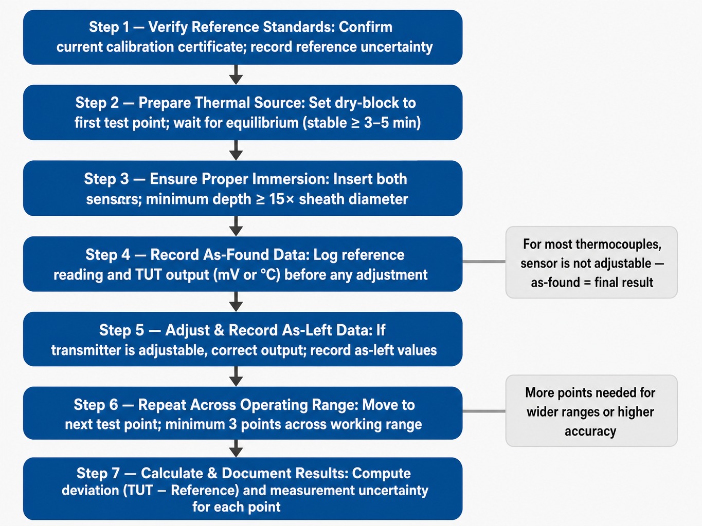
The complete thermocouple calibration procedure in seven sequential steps.
Inhomogeneity and Drift: The Two Factors That Invalidate Calibration Between Intervals
A thermocouple can pass a rigorous calibration in the lab and still produce inaccurate readings in the process. This happens because calibration verifies the sensor under specific, controlled conditions that may not reflect its installed state. The two primary culprits are inhomogeneity and drift, and most calibration programs dangerously underweight both.
Why Inhomogeneity Is the Dominant Uncertainty Contributor
A thermocouple works because the Seebeck coefficient the property that generates a thermoelectric voltage in response to a temperature difference is uniform along the length of its wires. Inhomogeneity occurs when this property is altered in one section of the wire due to chemical contamination, oxidation, mechanical stress, or repeated thermal cycling.
Here's the critical insight: a standard comparison calibration is performed at a specific immersion depth in a uniform temperature field. If the inhomogeneous section of the wire is outside the temperature gradient zone during calibration, its effect is invisible. But when that same sensor is installed in a process furnace with a different immersion depth and a different temperature gradient, that flawed section now contributes to the output, creating an error.
I once saw a Type K thermocouple that passed lab calibration at 500 °C with flying colors, but the same sensor read 3.2 °C high when installed in a process furnace at the same temperature. The cause was inhomogeneity introduced by repeated cycling in a reducing atmosphere. The damaged section of wire was never fully immersed during the lab calibration but sat right in the thermal gradient during process use. This is why a calibration certificate is not a guarantee of in-process accuracy. Specific failure modes like "green rot" in Type K thermocouples (preferential oxidation of chromium in low-oxygen environments from 800-1050 °C) are notorious for creating severe inhomogeneity.
What Causes Thermocouple Drift and How to Track It
Drift is distinct from inhomogeneity. It is a gradual, systematic shift in the thermocouple's output over time, usually in one direction. It's caused by the cumulative effects of high-temperature exposure and metallurgical changes in the wire.
Unlike inhomogeneity, drift is detectable through periodic calibration. It appears as a progressive increase or decrease in the as-found deviations across successive calibration cycles. This is why recording as-found data is so vital. If your calibration program diligently records this data, you can trend the drift rate for each individual sensor. This data is the most valuable output of your program, as it provides the evidence needed to move from arbitrary calibration schedules to risk-based recalibration intervals. For example, Type K thermocouples in high-temperature service drift faster than Type N, which was specifically designed for improved stability. Trending this data makes that difference visible and actionable.
Building a GUM-Compliant Uncertainty Budget for Thermocouple Calibration
An ISO/IEC 17025 auditor expects a calibration certificate to report the measurement uncertainty for each result. A certificate that simply states "Pass" or lists a deviation without an uncertainty value is incomplete. The uncertainty budget is the formal document that proves how that final uncertainty number was calculated, making it defensible.
Based on the Guide to the Expression of Uncertainty in Measurement (GUM), the primary uncertainty contributors for a comparison calibration include:
- Reference Thermometer Calibration: The uncertainty stated on your reference standard's own calibration certificate.
- Reference Thermometer Drift: An estimate of the standard's drift since its last calibration.
- Thermal Source Uniformity: The temperature gradients (both axial and radial) within the dry block or liquid bath. A dry-block calibrator and a liquid bath are not interchangeable at the uncertainty level; gradients inside a dry-block's bore are typically larger.
- Readout Resolution: The resolution of the instrument reading the reference and the unit under test.
- Measurement Repeatability: The standard deviation of repeated readings at each test point.
- Cold Junction Compensation (CJC) Error: The uncertainty of the internal CJC sensor in your readout instrument.
- Stem Conduction Error: If immersion depth is marginal, this error must be estimated and included.
This example is simplified for illustration. A robust thermocouple calibration uncertainty budget may include additional contributors depending on the method, instrumentation, and application.
These individual uncertainty components are combined using a root-sum-of-squares (RSS) method. The result is then multiplied by a coverage factor (typically k =2) to produce an expanded uncertainty with an approximate 95% confidence level. For a well-controlled comparison calibration of a base-metal thermocouple, a typical expanded uncertainty is in the range of 0.3 °C to 1.0 °C.
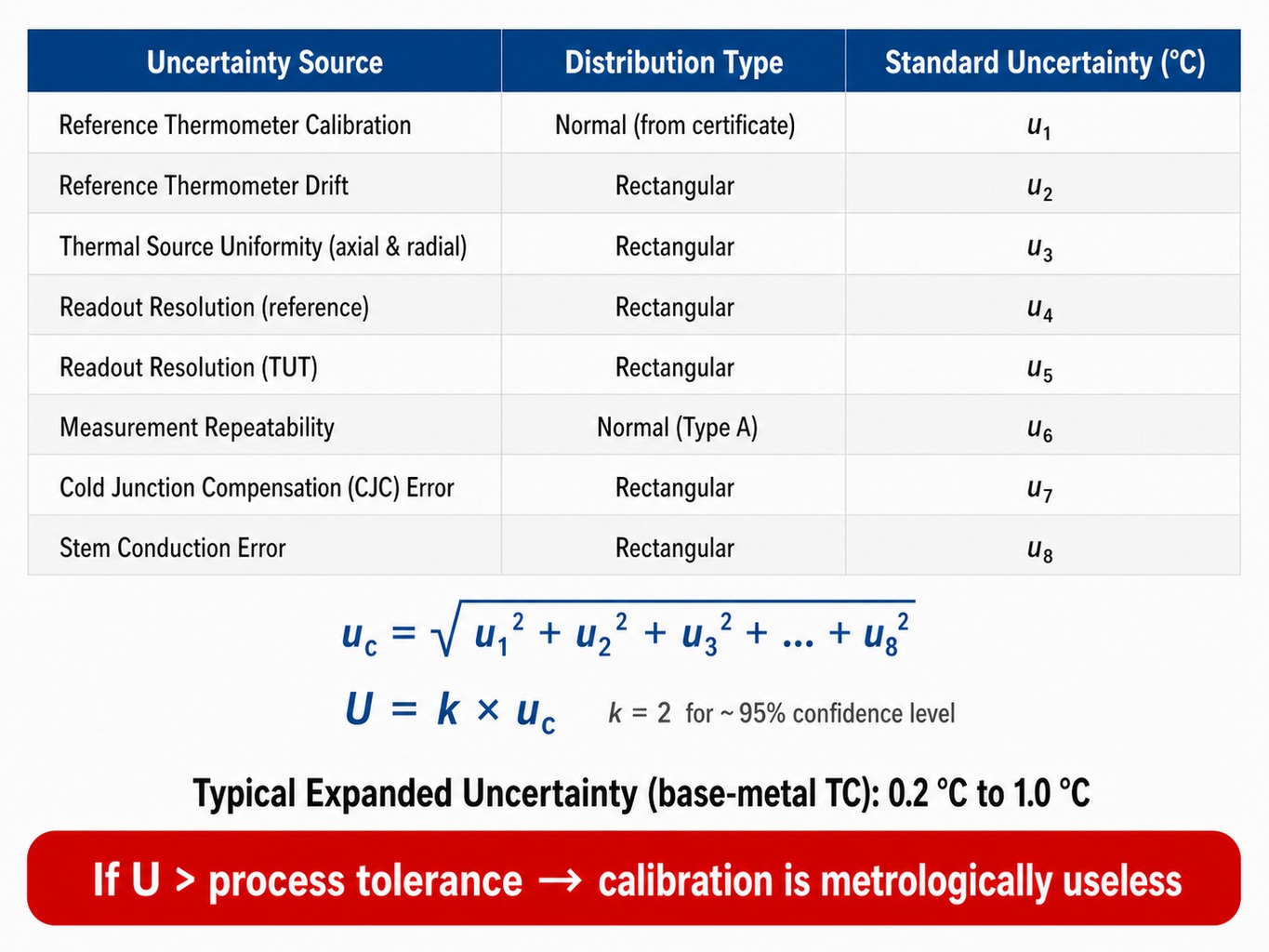
A defensible thermocouple calibration requires every uncertainty source documented and combined.
If this final expanded uncertainty is larger than your process tolerance, the calibration is metrologically useless, even if the sensor's deviation is zero. It means your measurement system isn't capable of proving compliance.
Setting Calibration Intervals Using Drift Data Instead of Arbitrary Schedules
Most thermocouple calibration intervals are set by tradition typically annually or by inheriting a previous quality manager's schedule. This is rarely optimal. Neither ASTM, IEC, nor ISO/IEC 17025 prescribes a universal interval; they require the organization to justify its intervals based on risk, usage, and historical performance.
The most defensible approach is to use the drift data your calibration program already generates. By plotting the as-found deviations from successive calibrations for each sensor, you create a drift trend.
- If a thermocouple consistently returns well within tolerance with a low drift rate, the interval can be safely extended.
- If the as-found data shows a trend approaching the tolerance limit, the interval must be shortened, or the sensor should be replaced.
This data-driven method replaces guesswork with evidence. It also addresses the hidden cost of over-calibrating. Every calibration event removes a sensor from service, introduces handling risk, and consumes labor and budget. For a heat-treat operation with dozens of thermocouples, eliminating unnecessary calibration cycles by justifying longer intervals for stable sensors represents a real gain in production uptime and efficiency.
What Auditors Actually Check in Thermocouple Calibration Records
Auditors don't evaluate whether a calibration was performed correctly; they evaluate whether the documentation proves it was performed correctly. A technically perfect calibration with poor records is, from a compliance standpoint, indistinguishable from no calibration at all.
When an assessor reviews your thermocouple calibration certificates, they are looking for specific elements. An accredited calibration provider like CTPM issues certificates where the uncertainty budget is derived, documented, and defensible, ensuring you can demonstrate metrological traceability without reconstructing evidence after the fact. Key elements include:
- Unique identification of the thermocouple.
- Identification of the reference standard(s) used and evidence of their traceability.
- The calibration method and environmental conditions.
- As-found and as-left data at each test point.
- The measurement result and its associated uncertainty .
- The date of calibration and the identity of the technician.
- Reference to the accreditation body (e.g., A2LA) and the lab's scope of accreditation.
The three most common audit findings related to thermocouple calibration are:
- Irrelevant Test Points: The calibration was performed at points (e.g., 0, 100, 200 °C) that do not reflect the sensor's actual operating range (e.g., 850-950 °C).
- Missing As-Found Data: Without this data, there is no way to assess the quality impact of a sensor that is discovered to be out-of-tolerance.
- No Uncertainty Statement: The certificate lacks a documented measurement uncertainty, or the uncertainty is not traceable to a formal budget.
When Your Calibration Program Needs More Than Certificates
This article has built the case that defensible thermocouple calibration depends on rigorous uncertainty analysis, evidence-based interval management, and audit-ready documentation. Many quality and engineering teams understand the "what" but lack the in-house metrology depth to execute the "how" to build GUM-compliant uncertainty budgets, analyze drift data, and ensure records will survive an ISO/IEC 17025 assessment.
This is where a technical services partner becomes essential. As an ISO/IEC 17025-accredited provider, CTPM approaches temperature calibration as a measurement assurance function, not just a certificate-generation service. Our team helps you interpret calibration data, develop defensible uncertainty budgets, and connect metrological evidence to process outcomes. With both lab-based and on-site calibration capabilities across the Midwest, we help you maintain measurement confidence without disrupting production.
Talk to CTPM about thermocouple calibration that stands up to audit scrutiny.
In the end, thermocouple calibration is a well-understood procedure. The difference between a compliant program and a truly defensible one, however, lies in mastering the details: understanding inhomogeneity, building traceable uncertainty budgets, using drift data to justify intervals, and producing records that answer the questions auditors actually ask.
A calibration certificate is not absolute evidence of accuracy. It is evidence of a comparison performed under specific conditions, and its value depends entirely on the metrological rigor and documentation that accompany it. Review your most recent thermocouple calibration certificate. Does it contain an uncertainty statement? Does it show as-found data? Do the test points match your process? If the answer to any of these is no, your program has a gap.
Frequently Asked Questions
Should I use a dry-block calibrator or a liquid bath for thermocouple calibration?
Liquid baths offer superior thermal uniformity and thus lower uncertainty, making them ideal for high-accuracy lab calibrations. Dry-block calibrators are far more practical for field and on-site work due to their portability and faster setup. For most industrial thermocouples, a quality dry-block calibrator provides sufficient accuracy, provided the bore fit is tight and immersion depth is adequate.
How do you account for cold junction compensation errors during thermocouple calibration?
If your readout uses internal Cold Junction Compensation (CJC), its accuracy (typically 0.2 °C to 1.0 °C) contributes to your total measurement uncertainty. For calibrations requiring lower uncertainty, using an external ice-point reference either a properly prepared ice bath or a commercial electronic ice-point cell is the best practice, as it eliminates CJC error as a significant variable.
Can you calibrate a thermocouple with a multimeter?
No. A multimeter can measure the millivolt (mV) output of a thermocouple, which serves as a basic functional check, but this is not a calibration. A true calibration requires comparison against a traceable reference thermometer in a controlled thermal source, a documented uncertainty analysis, and formal records that prove metrological traceability. A multimeter reading provides none of these.
What thermocouple types drift fastest and need more frequent recalibration?
Type K is the most widely used but also one of the most prone to drift, especially in high-temperature service (above 500 °C), due to oxidation and metallurgical instability. Type N was developed specifically to improve upon Type K's stability and drifts significantly less under similar conditions. Noble-metal types (S, R, B) are inherently very stable but can be contaminated at extreme temperatures.
How do you determine the minimum immersion depth for accurate thermocouple calibration?
A common rule of thumb is a minimum immersion depth of 15 to 20 times the outer diameter of the sensor's sheath. Insufficient immersion allows heat to conduct along the sheath away from the measuring junction (an effect called stem conduction), causing the thermocouple to read a temperature lower than the actual source temperature. This error must be quantified and included in the uncertainty budget if adequate immersion is not possible.