
Key Takeaways
- Zeroing a micrometer is not calibrating it; a zero check confirms one point but misses critical errors in parallelism, flatness, and accuracy across the measurement range.
- Accurate calibration requires a temperature-controlled environment (68°F / 20°C) and a thermal soak period for both the micrometer and gauge blocks to prevent thermal expansion errors.
- A proper calibration verifies accuracy at multiple points across the full range (e.g., a six-point check spread across different thimble positions) to detect non-uniform spindle wear and linearity errors that single-point checks miss.
- For quality systems like ISO 9001 or AS9100, in-house verification is often insufficient; you need traceable calibration certificates from an ISO/IEC 17025-accredited lab.
- Digital micrometers are not inherently more accurate than analog ones; the calibration process is still fundamentally mechanical, and display resolution should never be confused with instrument accuracy.
Most people who zero a micrometer before use believe they have calibrated it they have not. That quick check confirms agreement at a single point, but true calibration is a far more rigorous process. It confirms the instrument reads correctly across its entire range, checks for parallelism error between the anvil and spindle faces (with full flatness and parallelism tests available on request), and ties its results to a known standard.
This distinction is not academic. A micrometer can show a perfect zero and still produce significant errors at 0.250, 0.500, or 0.750 inches due to spindle wear, barrel bow, or face degradation. These are the errors that cause out-of-tolerance parts, failed assemblies, and costly audit findings.
This guide provides a complete procedure for how to calibrate a micrometer in-house, covering the critical checks most shop-floor guides skip. We will cover the tools, the step-by-step process for outside micrometers, and the crucial differences between in-house verification and the accredited calibration your quality system likely demands.
Why Zeroing Is Not Calibrating and What That Costs You
Zeroing a micrometer confirms one measurement point at the bottom of its range. It tells you nothing about parallelism error between the anvil and spindle faces, the flatness of those faces, or most critically the accuracy at any other point across the spindle's travel. This gap is where most measurement risk lives.
Consider a common scenario: a machinist zeros a 0–1 inch micrometer, confirming the zero line on the thimble aligns perfectly. They then measure a 0.750-inch diameter shaft and get a reading that passes inspection. What they don't know is that the micrometer has a slight barrel bow, causing it to read 0.0003 inches high in the upper half of its range. The part passes inspection but fails during final assembly, forcing rework and a production delay.
This isn't a rare edge case. Spindle thread wear is progressive and often non-uniform. A micrometer used frequently in a specific size range can develop a wear pattern that a zero check will never catch. A full-range check, however, exposes it immediately. There are three primary error sources that zeroing structurally cannot detect:
- Parallelism Error: The anvil and spindle faces are not perfectly parallel to each other.
- Flatness Error: One or both measuring faces are not perfectly flat.
- Linearity Error: The screw thread is worn unevenly, causing accuracy to vary across the measurement range.
Relying on a zero check alone is like inspecting only the first foot of a 100-foot cable. It confirms integrity at the start but provides no confidence about the rest of its working length.
What You Need on the Bench Before You Start
A micrometer calibration is only as good as its reference standard and the environment in which it's performed. Before you begin, gather the following and prepare your workspace.
Required Tools & Materials:
- Gauge Block Set: For most shop-floor verification, a set of ASME Grade AS-1 or Class K blocks is sufficient. The critical requirement is that the blocks themselves must have a current, valid calibration certificate with stated measurement uncertainty values.
- Lint-Free Cloths: For cleaning all measuring surfaces.
- Micrometer Stand or Fixture: A stand or V-block is essential for holding the micrometer. This prevents body heat from distorting the frame and ensures stable, repeatable measurements.
- Spanner Wrench: The wrench supplied with the micrometer for adjusting the barrel sleeve.
- Calibration Log: A dedicated logbook or software for recording as-found and as-left readings, date, technician, and instrument ID.
The most overlooked requirement is temperature. The international standard reference temperature for dimensional measurement is 68°F (20°C) per ISO 1. A steel micrometer and steel gauge block both expand at a rate of approximately 6.4 microinches per inch per degree Fahrenheit. If your micrometer has been sitting in a 78°F shop, a 1-inch measurement will read roughly 0.000064 inches high before you even touch the ratchet.
The Rule: Let the micrometer and gauge blocks thermally soak on the work surface, away from direct sunlight or heat sources, for at least 30 minutes before starting.
Step-by-Step Micrometer Calibration Procedure
This procedure applies to standard outside micrometers and follows established metrology practices consistent with standards like ASME B89.1.13. The goal is not just to confirm the micrometer reads correctly at one point, but to build confidence that it reads correctly everywhere across its range. This process works for both inch and metric micrometers.
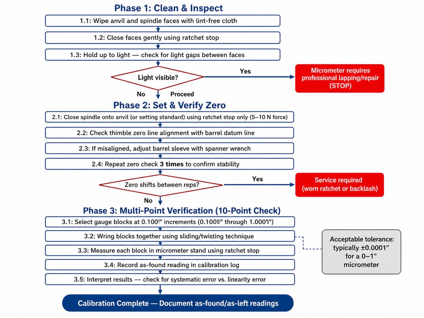
Clean and Inspect the Measuring Faces
First, wipe both the anvil and spindle faces with a clean, lint-free cloth. This is more than housekeeping, it is a critical inspection step.
With the faces clean, gently close a 0 to 1 inch micrometer using only the ratchet stop. Now, hold the micrometer up to a bright light source and look at the closed faces. If you can see light passing between them, you have a significant flatness or parallelism problem. No amount of zeroing can fix this, and the micrometer requires professional lapping and repair. Any visible scratches, nicks, or corrosion on the faces also disqualify the micrometer from reliable use.
Set and Verify the Zero Point
For a 0 to 1 inch, or 0 to 25 mm, micrometer, the zero point is set with the faces closed. For larger micrometers, use the supplied setting rod or a calibrated gauge block of the appropriate nominal size, such as a 1.000 inch block for a 1 to 2 inch micrometer.
- Apply Consistent Force: Gently close the spindle onto the anvil, or setting standard, using the ratchet stop, not the thimble. The ratchet stop applies a consistent measuring force, typically 5 to 10 Newtons, which is crucial for eliminating operator-to-operator variability. Listen for the distinct click of the ratchet.
- Check Alignment: Observe whether the zero line on the thimble aligns perfectly with the primary datum line on the barrel sleeve.
- Adjust if Necessary: If the lines do not align, use the spanner wrench to carefully loosen the barrel sleeve. Rotate the sleeve until the datum line aligns with the thimble's zero mark, then re-tighten it securely without over-torquing.
- Repeat the Check: After adjustment, repeat the zero check three times. If the zero point shifts between repetitions, the ratchet mechanism may be worn or the spindle threads may have excessive backlash. Both are conditions that require service, not further adjustment.
Verify Accuracy at Multiple Points Across the Range
This step separates a true calibration from a simple zero check. A multi-point check across the full spindle travel is standard calibration practice for catching linearity errors, barrel bow, and progressive wear. A common six-point approach uses five checks spread across the range at approximately 0°, 72°, 144°, 216°, and 288° of thimble rotation, plus one at full range. Checking at different thimble positions also provides a partial check for parallelism error.
- Select and Wring Gauge Blocks: Assemble a stack of gauge blocks for each checkpoint. Before measuring, you must wring the blocks together. Wringing is a specific technique of sliding two clean, flat surfaces together with a slight twisting motion until molecular adhesion holds them. A properly wrung stack feels solid and resists being pulled apart. A poorly wrung stack has air gaps that add significant error to your measurement.
- Measure and Record: Place the wrung gauge block stack in the micrometer, held in a stand, and measure it using the ratchet stop. Record the as-found reading in your calibration log.
- Repeat for All Checkpoints: Continue this process for all six points across the range, finishing with a point at full range, 1.000 inch on a 0 to 1 inch micrometer.
Interpreting the Results:
- Systematic Error: If all readings are consistently high or low by roughly the same amount, you likely have a zero offset that can be corrected by re-adjusting the barrel.
- Linearity Error: If the readings vary unpredictably, for example reading correctly at 0.200 inch, high at 0.500 inch, and low at 0.900 inch, you have a linearity or wear problem in the spindle screw. This cannot be fixed with a simple adjustment and indicates the micrometer needs professional service or replacement.
Depending on the instrument type, standard calibration procedures may also include additional steps for depth micrometers or tubular inside micrometers. For example, depth micrometers are typically checked with the shortest rod first, then each additional rod is verified at one point after the head accuracy is confirmed. Tubular inside micrometers are commonly checked using a gauge block stack and a figure-8 motion to identify the smallest valid reading at proper measuring force. Optional tests such as flatness, parallelism, base flatness, or spindle force may also be performed when a more detailed evaluation is required.
Acceptable tolerance limits depend on the micrometer's specification, typically ±0.0001 inch for a quality 0 to 1 inch micrometer, and the measurement uncertainty of your gauge blocks.
Digital vs. Analog Micrometers: What Changes in the Calibration Process
The fundamental calibration checks cleaning, face inspection, and multi-point gauge block verification are identical for both digital and analog micrometers because they assess the same mechanical components. The primary differences lie in the zero-setting mechanism and how you interpret the display.
Zero-Setting: On a digital micrometer, zero is set electronically by pressing a "ZERO/ABS" or "ORIGIN" button, rather than by mechanically rotating the barrel sleeve. This is faster but introduces a different risk. Many digital micrometers use incremental encoders, which means the zero point is reset every time the tool is powered off. This makes pre-use zeroing mandatory. Higher-end models with absolute encoders (common in Mitutoyo and Starrett series) retain their zero position through power cycles, which is more convenient but doesn't eliminate the need for periodic verification.
Resolution vs. Accuracy: This is a critical distinction. A digital micrometer displaying to five decimal places (0.00005") does not mean it is accurate to 0.00005". Accuracy is determined by the quality of the mechanical components the frame, spindle, and screw thread and is typically ±0.0001" for a 1-inch model with 0.0001" resolution or finer. A finer display does not tighten that limit, but a coarser one (0.001") widens it to ±0.0005", since tolerance can't be smaller than half the smallest graduation. The calibration procedure confirms the instrument's mechanical accuracy; the digital display only reports what the encoder reads. Pressing the "zero" button resets the display, but it does not fix a worn spindle or non-parallel faces.
How Thermal Drift and Shop-Floor Conditions Destroy Micrometer Accuracy
The most insidious source of error in dimensional measurement is thermal expansion. A quality inspector picks up a micrometer that was sitting on a sunny windowsill. The frame is at 85°F. The part being measured just came from a temperature-controlled CMM room and is at a stable 68°F. The inspector measures a 1-inch nominal diameter and gets a reading that is 0.00011" high. The part isn't wrong the micrometer is.
The mechanism is simple physics: steel expands at approximately 6.4 microinches per inch per degree Fahrenheit. That 17°F temperature difference on a 1-inch measurement produces roughly 109 microinches (0.00011") of thermal error. This error alone is larger than the entire accuracy specification of the instrument.
An even subtler problem is body heat. Holding a micrometer by its metal frame for just 30 seconds can transfer enough heat to raise its temperature by 1–2°F. On a 4-inch micrometer, this can create an error of 26–51 microinches. This is why experienced metrologists always use a mic stand or hold the instrument by its insulated grip.
Follow these three rules to control thermal error:
- Thermal Soak: Always allow micrometers, parts, and reference standards to acclimate to the same temperature for at least 30 minutes before critical measurements or calibration.
- Minimize Contact: Use a micrometer stand whenever possible. If you must hold it, use the insulated grip section only.
- Document Conditions: If your shop floor temperature varies more than ±4°F from the 68°F standard, note the ambient temperature on your calibration record.
Calibration vs. Verification: What Your Quality System Actually Requires
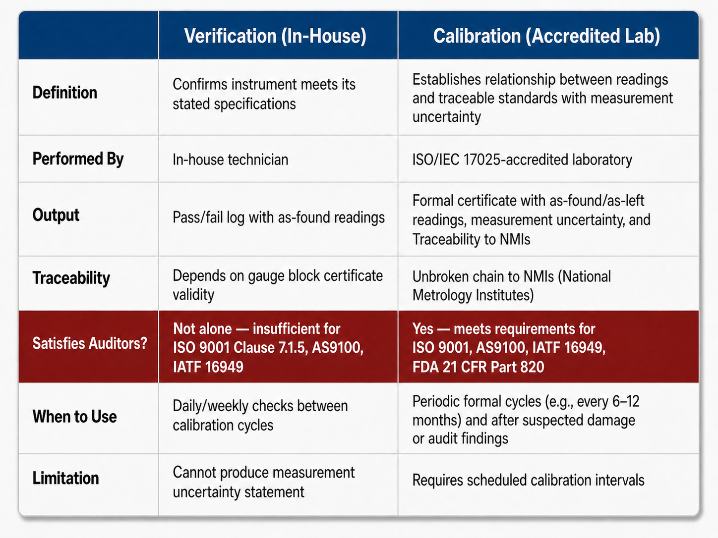
What most organizations call "in-house micrometer calibration" is, in formal terms, verification. Verification is the process of confirming that an instrument meets its stated specifications. Calibration, in the strict ISO/IEC 17025 sense, is a formal process that establishes the relationship between an instrument's readings and known values from traceable standards, complete with a calculated statement of measurement uncertainty.
Both are valuable, but they are not interchangeable and auditors know the difference.
During an AS9100 audit, an auditor asks to see the calibration certificate for a micrometer used on a flight-critical dimension. The quality manager proudly presents a detailed log of daily zero checks. The auditor writes a major nonconformance. The finding isn't because the micrometer was inaccurate, it is because the documentation fails to demonstrate traceability to national standards or provide a quantified measurement uncertainty. This single procedural gap can delay shipments and freeze production lots.
An in-house verification check tells you if a micrometer is safe to use today. It cannot, however, produce the traceable calibration certificate required by quality systems like ISO 9001 (Clause 7.1.5), AS9100, or IATF 16949. While in-house checks are highly effective for daily control, they do not replace the need for regular, accredited calibration intervals from a lab like CTPM to ensure audit defensibility, reduced risk, and absolute confidence in your measurements.
Read more: The Complete Guide to ISO/IEC 17025 Conformity Readiness | CTPM
When In-House Checks Are Not Enough
In-house verification is a legitimate and essential practice. It catches gross errors, confirms day-to-day usability, and reduces risk between formal calibration cycles. However, there are specific conditions where it is not sufficient.
You need formal, accredited calibration when:
- Your quality system requires it. ISO 9001, AS9100, IATF 16949, and FDA 21 CFR Part 820 all mandate traceable calibration with documented evidence.
- The measurement is critical. If the micrometer is used on dimensions where the tolerance-to-uncertainty ratio is tight, you need a defensible uncertainty value that only an accredited lab can provide.
- You suspect mechanical wear. If you detect parallelism, flatness, or linearity errors, you need an accredited lab to quantify the error and, if possible, perform repairs and lapping. When highly precise diagnostics are needed, a laboratory can evaluate anvil flatness and parallelism using monochromatic light and optical flats upon request. This is a specialized capability rather than a mandatory step for every standard accredited calibration.
- Your reference standards are expired. If your gauge blocks are past their calibration due date, your in-house checks are no longer traceable or trustworthy.
- You have an audit finding. A nonconformance related to calibration documentation or traceability is a clear signal that your in-house process is not meeting requirements.
In these situations, sending the micrometer to an ISO/IEC 17025-accredited calibration laboratory is the only way to obtain a certificate that will satisfy auditors, customers, and your own quality system.
How CTPM Supports Your Micrometer Calibration Program
CTPM provides ISO/IEC 17025-accredited dimensional calibration that produces the documentation your quality system demands. Our calibration certificates include as-found and as-left readings, a complete statement of measurement uncertainty, and clear traceability to National Metrology Institutes (NMIs), satisfying the most stringent audit requirements from systems like AS9100 and IATF 16949.
Our dimensional lab capabilities cover outside, inside, and depth micrometers, along with a vast range of other dimensional instruments. For organizations across Ohio and the Midwest that can't afford the downtime of shipping tools, our on-site calibration services bring accredited technicians directly to your facility.
Beyond just issuing a certificate, our metrology consulting team can help you establish effective in-house verification procedures and analyze drift data to optimize your calibration intervals to reduce measurement risk. We function as a technical extension of your quality team.
Conclusion
Calibrating a micrometer is not the same as zeroing it. The gap between those two activities is where measurement risk, audit exposure, and production errors accumulate. A proper calibration is a diagnostic process that verifies accuracy across the instrument's full range, accounts for environmental conditions, and produces documentation your quality system can defend. In-house verification is a valuable tool for keeping instruments safe between cycles, but accredited calibration is what keeps your measurements traceable and your audits clean. The organizations that master both are the ones that catch problems before they ever reach the customer.
Frequently Asked Questions
What gauge blocks do I need to calibrate a 0-1 inch micrometer?
You need gauge blocks covering six points across the range: five at sizes that fall at roughly 0°, 72°, 144°, 216°, and 288° of thimble rotation, plus one at full range (1.000"). For most shop-floor verification, ASME Grade AS-1 blocks are sufficient. The critical factor is that the blocks themselves must have a current, valid calibration certificate.
How do I account for measurement uncertainty when calibrating a micrometer in-house?
Your total uncertainty includes contributions from the gauge blocks, thermal effects, and operator repeatability. Because quantifying these factors in-house can be complex, many organizations rely on an ISO/IEC 17025-accredited laboratory to provide a complete, defensible statement of measurement uncertainty.
How often should a micrometer be calibrated in a production environment?
There is no universal interval. Most organizations start with a 6- or 12-month cycle and adjust based on historical data. If an instrument consistently returns in-tolerance, you can justify extending the interval. If it frequently drifts out, shorten it. Always document your rationale for auditors.
How do I check micrometer parallelism and flatness without specialized equipment?
For a quick shop-floor check, gently close the micrometer faces and hold them up to a strong light. If you see light passing between the faces, it indicates a significant parallelism or flatness error. While optical flats offer a more precise assessment, this light-gap test effectively catches gross errors.
What does traceability to National Metrology Institutes (NMIs) mean for a micrometer?
It means the measurement result can be connected through an unbroken chain of comparisons back to a national standard maintained by National Metrology Institutes (NMIs). Each link in that chain, from your micrometer to the gauge blocks used to check it, has a documented measurement uncertainty. This unbroken, documented chain is what gives a calibration certificate its authority.