
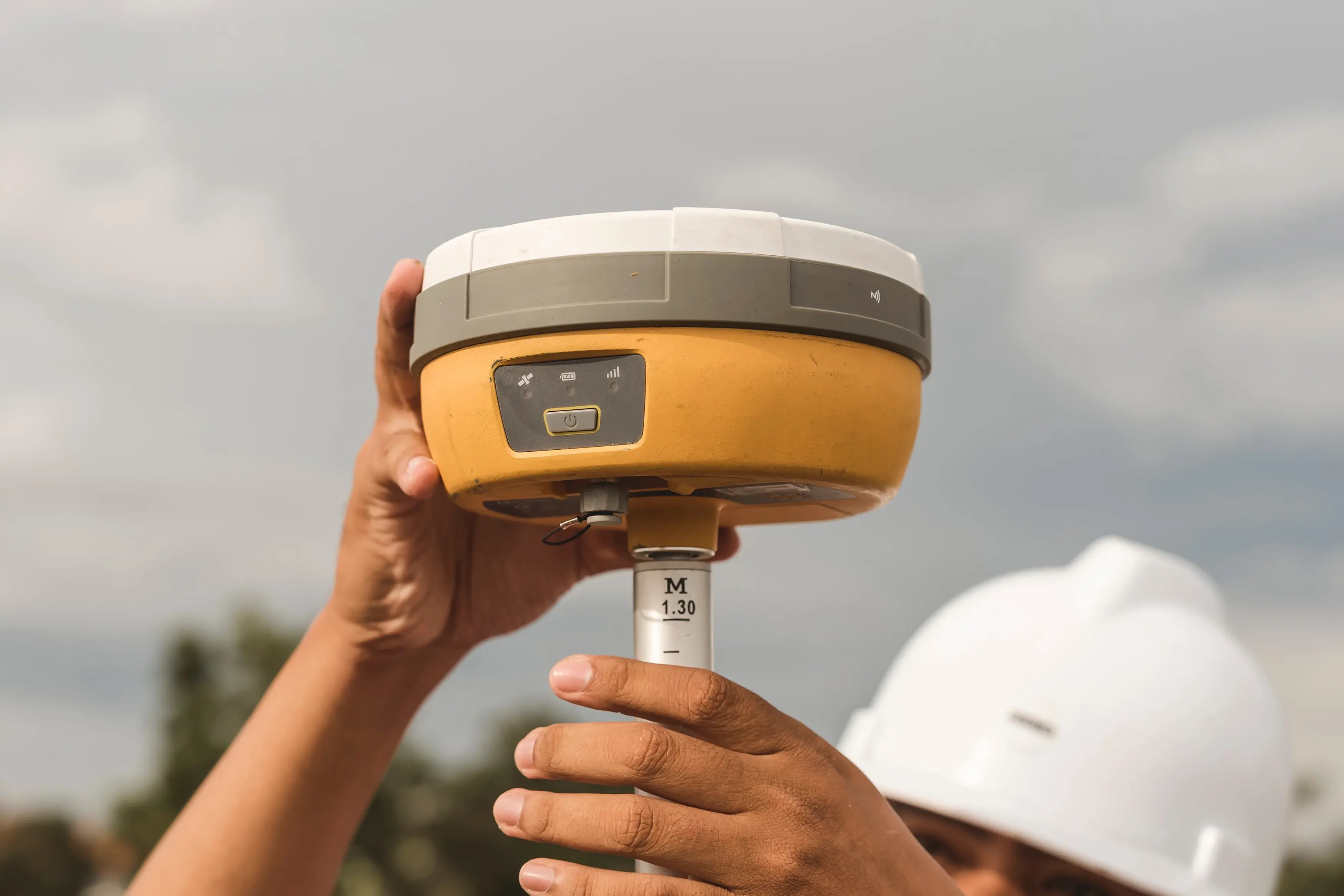
A survey crew on a construction site sets up their RTK rover, achieves a fixed solution, and logs points with what the data collector reports as 1-centimeter horizontal accuracy. The next morning, checking those points against a known control monument reveals that several are off by 3 to 4 centimeters. The immediate assumption is to blame multipath from a nearby structure or poor satellite geometry. But the receiver has not been calibrated in over two years, so the team has no current documented evidence that the equipment is still performing within its stated tolerances, and a calibration would likely have caught the problem earlier.
This scenario highlights a common misunderstanding. The centimeter-level accuracy of Real-Time Kinematic (RTK) positioning is a conditional specification, not a guarantee. While most field crews are skilled at managing environmental variables, one of the most controllable conditions is often the most neglected: whether the receiver and antenna still perform within their rated tolerances.
This article explains what the RTK GPS accuracy specification actually assumes, why field results diverge from the datasheet, and how calibration fits into the accuracy equation. We will also cover how to verify your equipment's performance and understand the error budget that defines your true positional confidence.
What RTK GPS Accuracy Specifications Actually Assume
Under manufacturer-specified conditions, a modern multi-constellation, multi-frequency RTK GNSS receiver can achieve horizontal accuracy of 8 mm + 1 ppm (parts per million) and vertical accuracy of 15 mm + 1 ppm (RMS). This level of performance, however, depends on a specific set of ideal conditions being met:
- A Fixed-Integer Solution: The receiver has successfully resolved carrier-phase ambiguities. A "float" solution is significantly less accurate.
- Short Baseline: The distance to the base station or network correction source is typically under 10-15 kilometers.
- Open Sky and Good Geometry: A low Position Dilution of Precision (PDOP) value indicates a favorable satellite constellation spread.
- Low Multipath Environment: The antenna is free from signal reflections caused by nearby buildings, vehicles, or water.
- Calibrated Equipment: Both the receiver and the geodetic-grade antenna are performing within their original design tolerances, with known and correctly applied antenna phase center offsets.
The "ppm" term in the specification accounts for distance-dependent errors. For every kilometer of baseline length between the base and rover, 1 ppm adds 1 mm of uncertainty. For example, at a 10 km baseline, the 1 ppm term adds 10 mm of error, so the total horizontal uncertainty for an 8 mm + 1 ppm receiver would be 18 mm (8 mm + 10 mm).
Vertical accuracy is almost always worse than horizontal typically by a factor of 1.5 to 2. This is a simple matter of geometry. Since satellites are only visible above the horizon, the vertical component of the satellite geometry (VDOP) is inherently weaker than the horizontal (HDOP), leading to greater uncertainty in elevation measurements.
Why Field Accuracy Diverges from Datasheet Specifications
The gap between datasheet accuracy and what you observe in the field is not random. It comes from specific, identifiable error sources that fall into two categories. The first, environmental factors, is familiar to most practitioners. The second, equipment condition, is systematically under-examined and often the source of hidden systematic bias.
Environmental and Observational Factors
Even with a perfectly performing receiver, field conditions can degrade RTK accuracy. These sources are well-understood but worth reviewing:
- Multipath: Signal reflections from buildings, vehicles, or even the ground can interfere with the direct satellite signal, causing position scatter. A rover set up just a few meters from a concrete retaining wall can experience multipath that adds 1–3 cm of error, even while reporting a fixed solution.
- Satellite Geometry: High PDOP values (typically above 2.5) indicate a poor geometric spread of visible satellites, which magnifies other errors. This is common near tree canopies or in urban canyons.
- Atmospheric Delays: The ionosphere and troposphere delay GNSS signals. While RTK models correct for these delays, the correction becomes less effective on longer baselines where atmospheric conditions at the base and rover diverge significantly.
- Correction Latency: The "age of corrections" from your base station or NTRIP network matters. If corrections are delayed by more than a few seconds, the rover's position solution begins to degrade.
Equipment-Side Factors Most Teams Overlook
Even when environmental conditions are perfect, the equipment itself can be the source of significant error. These factors are often invisible in the field and can only be identified through systematic verification and calibration.
Consider a survey crew running a multi-frequency RTK rover that consistently reports fixed solutions and sub-centimeter horizontal residuals. Suppose that when the same rover is brought to a network of NGS-published control monuments for a check on a short baseline under 1 km, the horizontal offsets come back at 18–22 mm, more than double the receiver's stated 8 mm + 1 ppm spec. In a case like this, a more plausible root cause would be a slightly bent range pole, an incorrect antenna height entry, or the wrong antenna model selected in the data collector.
Key equipment-side factors include:
- Antenna Setup and Model Selection Errors: Entering the wrong antenna height, selecting the wrong antenna model, or using a slightly bent range pole can introduce a systematic offset even when the receiver itself is functioning normally.
- Receiver Oscillator and Component Drift: The high-precision internal clocks and signal processing components that enable carrier-phase measurements can drift over time due to aging and thermal cycles. This degradation can affect the receiver's ability to resolve ambiguities and maintain a clean measurement.
- Firmware and Configuration Mismatches: Using an outdated firmware version or entering an incorrect antenna height are common sources of systematic error that are entirely within the user's control but can go unnoticed without a rigorous verification process.
How Calibration Directly Affects RTK Positioning Confidence
The equipment-side factors just described antenna drift, receiver degradation, configuration integrity are precisely what a formal calibration process is designed to detect and quantify. Calibration of RTK GNSS equipment is not about making a receiver more accurate; it is about providing documented evidence that the receiver still performs within its manufacturer-stated accuracy specifications.
When an RTK receiver drifts outside its stated accuracy specification without detection, every survey point collected carries an unquantified bias. If that bias is found only after construction layout or as-built submission, the affected points must be re-surveyed and the related deliverables revised.
What GNSS Calibration Verifies and Why It Matters for RTK
A formal calibration of a GNSS receiver is a controlled process of comparing the receiver's position solutions against known, traceable reference standards. Typical calibration procedures involve collecting data over multiple, precisely known baselines of varying lengths, using repeated occupations and varying observation durations to assess both accuracy and repeatability under controlled conditions. The specific baselines, observation durations, and reference standards used vary by calibration provider and procedure.
Read more: GNSS Calibration Services | CTPM
The key output is not an "adjustment" but a report that quantifies the receiver's measurement uncertainty the statistical range within which the receiver's reported position can be trusted to fall. This value provides the objective evidence needed to determine if the receiver still meets its datasheet specification. Without a current calibration certificate, that evidence does not exist.
Calibration Intervals and the Reality of Equipment Drift
There is no single universal answer for how often an RTK receiver should be calibrated. The decision depends on manufacturer recommendations, your organization's quality system requirements, and the risk tolerance of your projects.
As a general guide, most organizations using survey-grade GNSS equipment for precision work follow a 12- to 24-month calibration interval. Shorter intervals are often warranted in specific situations:
- After the equipment sustains a significant physical impact (e.g., a rover pole is dropped).
- Following a major firmware update that could affect internal processing.
- When the equipment is used for high-stakes applications where measurement integrity is critical for project acceptance.
For instance, a construction firm using RTK for machine control on a highway grading project has a much lower tolerance for error than a utility company using the same receiver for asset mapping. The calibration interval should be managed as a risk-control decision, not just a calendar reminder.
How to Verify RTK Accuracy Against Known Control Points
While formal calibration is typically performed by a lab with traceable standards, field verification is a practical quality check that many survey and construction teams perform regularly. Verification is not a substitute for calibration, but it provides an essential check that your equipment is performing as expected between calibration cycles.
The process is straightforward:
- Select a Known Control Point: Use a published NGS control monument, a project control point with well-established coordinates, or a point you have previously surveyed with redundant, high-accuracy methods.
- Collect Observations: Set up your rover over the point and collect RTK data. Ensure you achieve a fixed solution and allow for a sufficient occupation time. Re-initialize the receiver to confirm the solution repeats, following your organization's documented procedure for the number of repeat occupations.
- Compare the Results: Compare the coordinates derived from your RTK measurement against the known coordinates of the control point.
From there, compare the horizontal and vertical differences, or residuals, together with the uncertainty of your measurement and of the control point, against the receiver's manufacturer-stated accuracy specification. If your residuals consistently run larger than that specification across multiple checks, it may indicate an issue with your equipment, your correction source, or your field procedures that requires further investigation. A survey manager who logs these daily check-in residuals in a simple spreadsheet can create a performance trend over time, revealing equipment drift long before it becomes a project-wide problem.
A Simplified RTK Error Budget: How Uncertainty Contributors Add Up
Understanding true RTK accuracy requires thinking in terms of an error budget a structured accounting of every factor that contributes to the total measurement uncertainty. Even if each individual contributor is small, they can combine to push your final position outside of tolerance.
Here is a simplified example of an error budget for a single RTK position measurement on a construction site:
- Receiver Measurement Uncertainty (from calibration): 8 mm
- Antenna Phase Center Uncertainty: 3 mm
- Base Station Coordinate Uncertainty (from CORS network): 5 mm
- Centering/Plumb Error at Rover Pole: 4 mm
- Multipath Contribution (moderate environment): 7 mm
These contributors do not simply add up. They are typically combined using a statistical method like the root-sum-of-squares (RSS). The key insight is that total uncertainty is driven by multiple factors, and the receiver's base accuracy is only one of them. Controlling each contributor especially the equipment-related ones confirmed through calibration is essential for maintaining high confidence in your final position.
Disclaimer: This example is simplified for illustration. A robust uncertainty analysis performed in accordance with metrological standards may include many more contributors, such as tropospheric and ionospheric residual errors, satellite orbit and clock errors, and the uncertainty of the reference standards themselves.
When RTK Accuracy Depends on More Than Field Conditions
The central tension of RTK positioning is that its datasheet accuracy is conditional, and the equipment-side conditions are the ones most teams under-manage. Current calibration data is what documents whether those equipment-side conditions are still being met.
For teams that need to understand whether their RTK equipment still meets its stated accuracy, quantify equipment-contributed uncertainty for their error budgets, or establish defensible calibration intervals, a calibration provider can help answer those questions. CTPM offers GPS/GNSS and survey-equipment calibration and can help teams interpret RTK accuracy data. Calibration work in other disciplines, such as metrology, is covered under its own separate scope.
Contact CTPM to discuss your RTK equipment calibration and accuracy verification needs.
Conclusion
The 1-2 centimeter accuracy of RTK GPS is achievable, but it is not automatic. It is the result of a chain of factors working correctly, from the satellite constellation down to the point of the rover pole, and every link in that chain has to hold for the datasheet number to apply in the field.
A fixed-integer ambiguity solution is a necessary condition for centimeter-level accuracy, but it is not a sufficient one; the receiver and antenna must also still perform within their rated tolerances. Treating calibration as part of your accuracy management workflow means your measurements are backed by documentation when they are reviewed on the jobsite, in the project deliverable, and during an audit.
Frequently Asked Questions
What is the difference between RTK fixed and float accuracy?
A fixed solution means the receiver has resolved integer ambiguities in the carrier-phase measurements, achieving its stated datasheet accuracy (typically 1-2 cm horizontal). A float solution means ambiguities are unresolved; accuracy degrades significantly to the decimeter or meter range (10-50 cm or worse). Always check the solution status before trusting an RTK measurement.
Does antenna calibration affect RTK GPS accuracy?
Yes, significantly. Every GNSS antenna has a phase center that shifts with satellite angle and signal frequency. If the antenna's calibration model is incorrect or outdated, every measurement inherits a systematic bias, often several millimeters vertically. Using the correct, current antenna model in your data collector is essential for achieving rated RTK accuracy.
Is PPK more accurate than RTK?
PPK (Post-Processed Kinematic) and RTK use the same measurement principles and can achieve similar accuracy under comparable conditions. PPK sometimes produces a more robust solution because the data is processed forward and backward in time, and the two passes are combined, which can help bridge brief signal interruptions. The practical difference is workflow: RTK provides results in real-time, while PPK requires office processing.
Can multipath errors be reduced on construction sites?
Multipath can be mitigated but not eliminated. Practical steps include keeping the antenna away from reflective surfaces (buildings, vehicles), using an antenna with a ground plane, setting a satellite elevation mask of 10-15 degrees, and using occupation times long enough for errors to average out. Site awareness remains the most effective tool.
How do CORS networks and NTRIP services affect RTK correction quality?
CORS (Continuously Operating Reference Stations) provide correction data via NTRIP, eliminating the need for a local base station. Correction quality depends on the network's density, the distance to the nearest station, and data latency. Network RTK solutions like VRS or MAC can improve accuracy over longer baselines by modeling corrections specifically for the rover's location.